| Güde
Easy 170 (MIG/MAG gas / nogas) Repair And Upgrade last update: Oct 17, 2021 Copyright
2021-23 by H. Gragger. All Rights Reserved. All
information provided herein is destined for
educational and D.I.Y. purposes only. Commercial
re-sale, distribution or usage of artwork
without explicit written permission of the
author is strictly prohibited. The original
units with their associated
trade-names are subject to the copyright of the
individual copyright owner. The Author is by no
means affiliated with any of those companies.
References to trade names are made for
educational purposes only. By reading the
information provided here you agree to the Terms
of Use.
|
||||||||||||||||||||||||||||||||||||||||||||
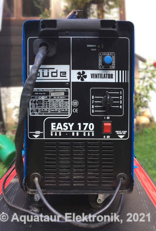
| MAIN PAGE>GUEDE_MIG_EASY_170 Index Introduction Although I will soon go back to my
roots by means of language (i.e. German) there is so
incredibly much helpful information to be found from
mostly the English speaking welding community. So this
is my homage to all you guys out there.
A decade ago I felt like learning to weld, and I had bought a huge used professional MIG / MAG welder from ELIN. Surely a brute. I did (and still do) not have a suitable indoor room that would allow for welding without setting something on fire, so my adventures are restricted to outdoor activities. It was too early, time was not right yet. I gave it away to my brother. The very same brother recently found a Güde Easy 170 gas / nogas MIG/MAG unit standing at the scrapyard, looking like new and waiting to be salvaged. He took it home and found that it worked somehow, but appeared to have no ooomph. Since he has welders galore anyway, I decided to try to repair it for myself. A new epoch opened up for me - the iron age. There is many a thing I discovered through many an hour I spent on the internet, and the outcomings may be of interest for y´all and may give you a steeper learning curve.
Back
To Index
Back To Index
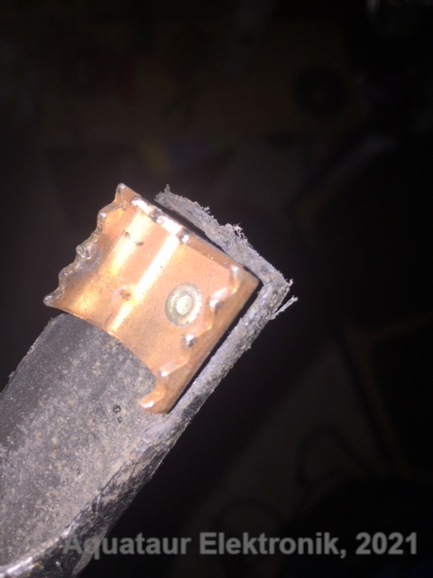
The Welding Rectifier I was totally unknowledgeable as far as the interior of welders goes. However, being a trained engineer of electronics, a first look inside with a "technical" eye revealed a huge transformer with taps going to a beefy front panel switch, a choke, a feeble control panel, a fan, and a rectifier with a heat sink. Since there was voltage on the secondary, I looked closer at the rectifier. Some diodes had their connective leads blown, one was fallen off, so clearly - the rectifier needed some attention. First idea was to find those press-fit diodes, however the crystal ball was ignorant about their type. On welding sites some guys were retrofitting rectifiers into their welders, mainly simple old-school AC stick welders. The routes taken were mainly:
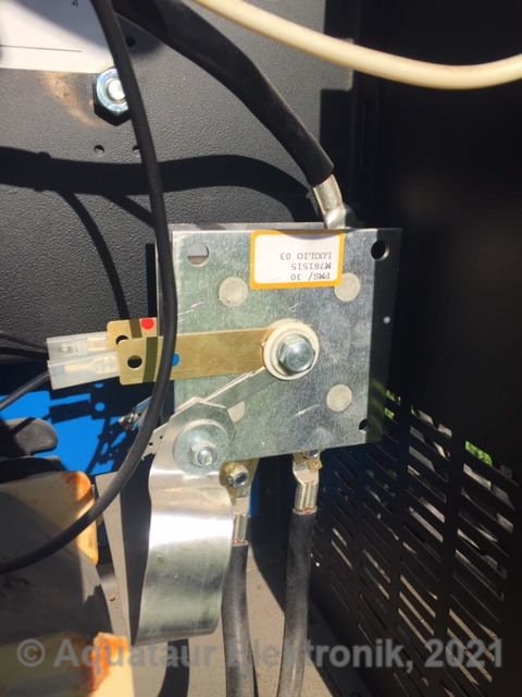
Indeed there are lots of scribblings in Italian inside the machine, so this was definitely assembled in Italy. SCOMES is an Italian company[1] (and indeed, very many companies to do with welding are located in Italy) that mainly produces welding rectifiers. Be prepared that they don´t speak to you. They refused to communicate or were not very helpful (practically all of them), either because of the language (I wrote in English to them) or just because of sheer arrogance towards foreigners. Hard to tell. Maybe they only talk to you if you promise to take hundreds of units. However, you find the numbers there and then you can go hunting the web. Indeed you will find the diodes[2] (they are allegedly used in car alternators), but
By the way,
the number of plates
indicates the number
of phases:
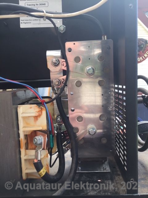
2... single phase (what they call monophase, like in PMS xx) 3... dual phase: I don´t see it on their list, but a dealer here has one and he says, that there are half-bread machines that are not quite three-phase, but use two phases for more power. 4... three phase. This can be helpful, because their catalog is not very explanatory. The PMS-180 can deliver 180 A at a 60% duty cycle (see explanation below) and has 20 diodes, the defective one had 8 diodes. The latter is no longer listed, but logic dictates that it was on the lower side power-wise and was certainly pushed to the limit. The bill was paid... The price was ridiculously low at about 50 Euros, and the 120 Ampere type (PMS-120) would cost hardly any less. Sometimes the things you buy bear no relation to the price tag - both ways... Duty cycle is always measured in 10 minute intervals. A 60% duty cycle thus means, you can weld at the rated current for 6 minutes and must maintain a 4 minute cooling period, or the machine will cut out by thermal overload. This is further subject to several other variables[3].
Paralleling diodes might create some hazard: do they really share the current? What if one has a lower threshold, does it not tend to take the major current load and burn out? Let´s look at this subject:
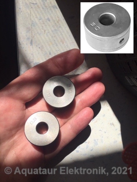
Since I planned to use flux
(cored) wire without gas, a.k.a. self
shielded flux wire (Deutsch:
selbstschützender
Fülldraht), I
needed the appropriate
rollers.
Note that you probably need a different liner for #010629 (aluminium welding), plus the power will probably be too low for aluminium. Same applies for 1.0 to 1.2 mm wire. There is a reason the machine comes stock with 06/08 steel. Note that you probably need a different liner for #010629 (aluminium welding), plus the power will probably be too low for aluminium. Same applies for 1.0 and 1.2 mm wire. There is a reason the machine comes stock with 06/08 steel. DECA refused to answer my questions in a way that was helpful and were not very friendly overall. I had to jump in at the deep end for the rollers and bought them from a local Italian shop who had them on the ´bay. They indeed did not answer my questions on the dimensions too, despite several attempts. Hmm. Well they were cheap enough for 10 Euros each. They sent me #010627 which has two knurled grooves stamped 0.6 and 0.8, so it looks that both 0.8 and 0.9 are meant to run on the 0.8 groove. And they do. I then found the same rollers to be used in another machine made by ELMAG for their Euromig 160 series (the pictures don´t fit the descriptions btw.) for four times price; that´s how to make money out of nuthin...
Beware: Clarke has similar design rollers (screw mounted type), but those have a different bore (9mm vs. 10mm). Unfortunately, if this wire feed unit decides to fail on day, a different replacement unit with a 24 Vdc drive will have to be installed. These days they are made of metal rather than plastic for the relevant parts. I recommend inquiring about the rollers used beforehand, to have a supply at hand if needed. The fact the MIG 170 and Easy MIG units were equipped with DECA rollers (and presumably a wire feed drive made by them) plus the fact that the machine was internally full of Italian scribblings made me think that DECA built it originally, but a welder salesman with experience remembered that Güde welders were built by CEM (likely coincident with CEMONT), but later outsourced to Slovakia. Indeed CEM style welding accessories are sold by Chicago Electric / Harbor Freight and others. Then there is the Trafimet company (maker of the work clamp I used), which is Italian too. Funny there is so much welding stuff built in Italy. All those entry-level units use peripherals that look darn similar, they all seem to use the same components. Back To Index The
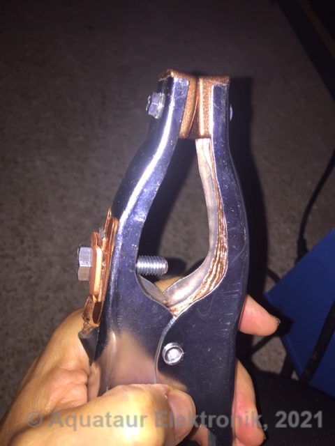
Work (-Lead) Clamp Is Not A Ground
(Earth) Clamp
... and the workpiece lead (wire) is not a ground lead...
They are however somewhat clumsy in their description, because they show a picture of such a clamp right beside the paragraph, where they advise against calling it grounding clamp. This is as useless as a double negation to a child. The apparatus´ case itself is certainly earthed, but there is NO earth connection to the transformer secondary anywhere. Kind of an insulation transformer. Any electrical device that is not double insulated, i.e. any device that has a metal case has to be grounded (earthed). This is according to standard safety regulations and is valid for all electric appliances. However, the welding voltage itself is not normally earthed, because it is subject to different regulations:
But note: this is valid only for those states, that are subject to ANSI Z49.1! In Europe (Germany) they strictly state that a welding table must not be earthed! (BGI 553, Abs. 3.5) The term "ground" is wrong for other reasons too:
It is a sad
fact that many manufacturers or dedicated
welding sites keep mixing up that nomenclature
and thus add to the confusion, but Lincoln has
it right! You are well advised to adhere to the
official safety regulations and not to those
sites, and indeed my writings. As a
short aside: for earthing, from what I
deduct, most hazards associated with often
quoted stray currents (for either the welder or
the line grid installation) come from
Neither is
the case for MIG/MAG machines (except maybe the
second one, if you repair your tractor), so we
are relatively safe. But back to
right nomenclature for the clamp: it is more
aptly be called "work lead clamp" or "work
clamp" and "work lead". It is the return
current line. This eliminates all
potential for confusion.
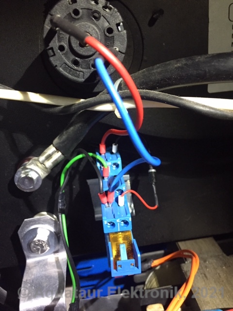
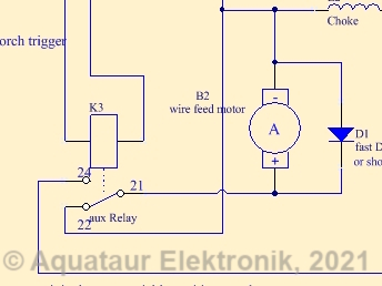
Back To Index Wire Feed Overrun And The Cure This welder´s design tries to be efficient while being effective. In so far those designs are so minimalistic that they are fail-safe and brilliant. But it turns out that most of those simple units suffer from certain peculiarities. Some are harmless, some annoying. Originally, the wire feed circuitry is connected directly to the power rectifiers output. Pulling the trigger would activate the welding supply by means of the primary relay besides simultaneously activating the wire feed. Looking closely, this takes a fraction of a second to get going, but this is not usually a problem. Fellows have noticed (like me) that the feed motor continues to run an indefinite time after releasing the torch trigger, spouting out wire. Now this is a problem, because you have to aim for a constant CTWD[7] (Contact Tip to Work Distance, a.k.a. known as stick-out; both terms bear the potential of misconception by the way) throughout. I found myself more trimming wire than welding wire, particularly when tacking... The problem arises, because the motor is wired directly to the DC supply and has no low resistance path to get rid of the energy stored in its inductance, once the trigger is released. Every DC Motor needs to be braked in a controlled way or it will overrun. This lead to a modification known as the wire feed mod[8]. This simple mod utilizes a small auxiliary relay, slaved after the primary relay (230V type). It has to have a SPDT contact at least.
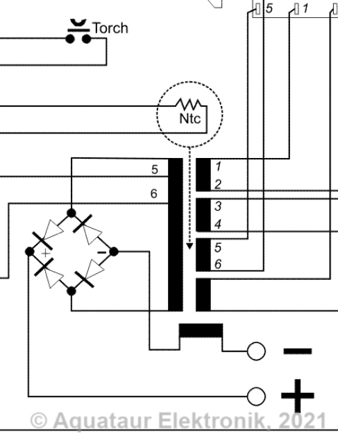
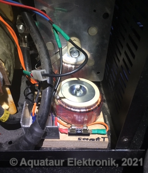
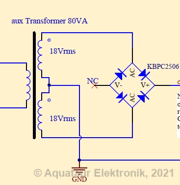
Needless to say, this mod stops the motor dead in its tracks. An effective mod by all means and really worth while. Back To Index Erratic Wire Feed And The Cure The transformer secondary on the Güde that provides the welding current, after the rectifier, produces a voltage between 19 Vdc and 28 Vdc (open loop) - basically an ideal range for the small DC motor that drives the wire feed unit. Unfortunately that voltage varies with the tap chosen on the primary, which is de facto a power setting. A higher power setting will invariably increase the wire feed speed (hereafter: WFS). This comes out as a faux synergistic effect, since higher voltage needs higher current settings anyways and thus is not necessarily problematic, although real synergistic welder units will actively fiddle with that due to tried and tested parameters from program presets. Note: those voltage values were measured by a cheap digital volt-meter. #1 this device uses a certain crest factor for calculating the values, meaning it relies on a sinusoidal wave form of 50 Hz, while the rectified waveform has 100 Hz. #2 the values are measured under no-load conditions, meaning the voltage sag upon application of a load is not considered. Therefore, those values are only rough estimations and will invariably be incorrect.Some guys have noticed that peculiarity and thought this was something that needs to be remedied and installed a separate supply of sorts for the motor. Arc geometry (linked to voltage) and current (linked to WFS) are strongly intertwined, particularly in the short-circuit welding or short-arc welding mode we are concerned here with. This is a kind of self-regulating process. The faux synergistic effect works not bad on the Güde, but some machines seem to suffer from the voltage sag under load so badly, that the WFS becomes erratic to a point of being unusable (SIP and COSMO machines). That said, it was noticeable on the Güde too, and particularly annoying when starting with laying a bead. With MIG 170, which apparently is a direct successor to the EASY 170 device being dealt with here, Güde have made a change to the welding transformer secondary by spending a small additional winding for the wire feed motor. They have by the way also made changes to the speed control electronics on the front panel (like using an encoder instead of a potentiometer). Note that the speed control circuitry has no galvanic connection to the output transformer leads, like it did on the EASY 170 model (common minus potential, look at the schematic above). It is therefore floating. This is different from the mods shown in a welding forum (post #176). This decision does not interfere with the primary relay control circuitry on the front panel as this has (to have) its own supply, fed by the small transformer / rectifier assembly you typically find on those boards. This circuitry also produces the low (presumably 12 or 24 V) control signal that goes to the torch trigger. They are all isolated from each other. So it becomes very easy to provide a stable voltage to the speed control assembly just by cutting the leads to the original (welding-) transformer / rectifier and inserting a dedicated transformer / rectifier for the motor circuitry. I do not like the idea of using a switchmode power supply left over from a defunct laptop. Although workable, a welder is a blunt instrument and everything inside has to be rugged, and a SMPSU belongs onto a desktop and not inside a welder. A transformer and a rectifier play in the same league as the welder.The DC Motor present in the Güde has a comparably small current demand, it only uses 500 mA @ 20 Vdc at full throttle (equivalent to 10 W, which suggests it genuinely is a 15 W unit as some claimed) which is small compared to bigger machine´s 90W brutes (that look deceptively like a windshield wiper motor). By the looks of it, those little machines all use the same motors. Bigger machines use bigger motors, but those very likely have a properly designed driving circuit that needs no upgrade, resulting in a whole different price-segment. I had a custom wound 80VA transformer lying around that are just fine power-wise. It has two secondaries rated at 18V full-load, but for a system that just uses a FWCT rectifier and no capacitor, and a light load, it was kind of hard to anticipate, if the resulting motor speed was in the right range or not. It turns out, the range is perfect. In many welder forum pages that perform this mod people bought 24 Vac transformers, and while this does not hurt technically, it shifts the drive circuit to excessive speeds. They then had to fumble with the drive circuit. Keep in mind that the transformer ratings specify 24 Vac at full load, so at no or light load this may rise another volt. Those values are referring to a crest-factor of a sinusoidal wave, meaning the peak values are by a factor of 1.4 higher or even more, since we have 100 (resp. 120) Hz after the rectifier. So the motor control board might see some 32 Volts.
The rectifier I had, a KPBC2506 (25A, 600V) is an overkill too, but it does not harm. The (-) terminal is left open. If I had to buy a transformer, I may strive for a single 20 Vrms secondary (being a stock value) and a bridge like the above to make for a full wave bridge rectified arrangement. Since you can safely assume that all drive units installed in those little machines you ever are liable to meet (in case you have to swap one out) use motors in that power range, there is little need to prepare for dramatically bigger motors. In the lights of that, 100 VA, as many modders have suggested, appear like a total overkill and a waste. For Güde Easy 170 a recommended mod, for MIG 170 not necessary. This modification was another 100% success. Very steady wire speed. The estimated "center" speed value (as it works out from the total available voltage) appears no different than before, so I believe the 18Vrms secondary is a good choice. There is no need to change any trim pots. Back To Index Burnback Despite fixing the motor overrun problem, the welding current persists a fraction of a second after releasing the trigger. I made a request in a welding forum and a friendly mate turned me onto the right key-word: burnback. Unfortunately this can mean two things: #1 the wire burning back into the contact tip due to false settings or false usage or #2 a controlled amount of burn-back after the trigger is released. It is the latter we are concerned with and the amount of control thereof. I noticed that both after pushing the trigger knob and releasing it, there is a delay of a fraction of a second until a reaction appears. This delay is unconsequential upon starting and probably helpful by establishing proper gas-flow before igniting the arc, however after releasing the welding voltage remains active for the same period of time. The way it is wired means that there will be a certain amount of wire spouted out too. This has a very logical and comprehensible reason:
The way this is ensured is by putting an electrolytic capacitor in parallel to the relay coil. Now that could be fixed by separating the mains relay from the motor relay and adding different time constants to the motor relay. That said, once a certain setting has been found, any change in any other parameter will render this setting futile again. So for the most, you can find a burnback control setting that works only for a given setting of the other parameters, and that will give you freedom for exactly that one job. In the end, you probably have one control more to worry about...
You can twist this every way you wish, it probably boils down to just that:
That said, I looked what can be done on the Güde. After a day of reverse engineering the control PCB, I know their schematic inside out. It is not as basic as some SIP machines appear to have it, but still crude enough that a burnback feature cannot be incorporated without unreasonable effort (meaning: a completely reworked control board). What is needed is a true off delay timer relay for the welding transformer primary similar to the way shown here[9] .Back To Index Thermal
Management
The way they have mounted the ventilation fan is far from effective. The fan itself may be capable, but it is mounted to the front panel with a 2 cm distance. Together with a slotted grille, this will reflect some of the airstream back into the casing. Like it is done on any PC power supply, they should have made a dedicated full cutout on the outlet panel with an x-braced finger protection grid or at least an equivalent cut-out. All other panel holes should be barred, or the airstream will take the short way back in right around the fan. This measure would leave the airstream no option as to where it can go out and produce a defined suction through the back panel. This is well known and of huge importance in devices like PC cases. Doing this properly would have amounted to zero extra cost, just a matter of design. You can of course fix that if you experience frequent temperature cut-out. The damaged rectifier, besides being on the very small end all over, was hidden above the back panel grille cutout area, so there was not much airflow to cool it. The bigger one I have installed is seated right in front of the grille now. Back To Index Pro vs. Hobbyist Grade And
Upgrade
Very soon I found out what
distinguishes a hobbyist welder from a
pro device:
That said, there is a guy who did all this to his MIG 170[10] by adding
Again, you
decide whether that is worth the effort. Verdict I learned a tremendous amount on how welders work in general and how those transformer-based units work. Note I highlight transformer-based, because contemporary units are inverters, meaning they are mostly all-silicon. Such stuff usually is full of bells and whistles, programs that let even a beginner weld good (so they promise...), but let some decades go by, like on the unit I speak about above, what will be with those electronic gew-gaws? Should I ever feel the need for something bigger or more flexible, I would know what key elements to look at. Back To Index Reference Note that most of them are manufacturers and won´t sell to you directly. But you will find the information you need there. [1] SCOMES, http://www.scomes.com/en/products/pressfitted-diodes-rectifiers/single-phase-bridge-rectifiers/ [2] ROSEN rectifiers, https://www.power-thyristor.com/welder-rectifier-diode/ [3] Welding Answers: Understanding Duty Cycle, https://weldinganswers.com/understanding-duty-cycle/ [4] DECA welding, https://www.decaweld.com/ [5] Snipsmag: The importance of good work lead connections, www.snipsmag.com/articles/85102-the-importance-of-good-work-lead-connections-when-welding [6] SACIT (a TRAFIMET company), http://www.sacit.com/ground-clamp-for-welding/ [7] ESO vs. CTWD, https://www.lincolnelectric.com/en-us/support/welding-solutions/Pages/eso-vs-ctwd.aspx and Material Welding: What is Welding Electrode Stickout for GMAW & TIG? https://www.materialwelding.com/what-is-welding-electrode-stickout-for-gmaw-tig/ [8] MIG Welding Forum: SIP 130 wire-feed power supply - alternative approach, https://www.mig-welding.co.uk/forum/threads/sip-130-wire-feed-power-supply-alternative-approach.11532/ [9] Miller Welding Forum, user Vicegrip: DIY Pre and Post flow controller for Mig machines, https://forum.millerwelds.com/forum/welding-discussions/13166-diy-pre-and-post-flow-controller-for-mig-machines [10] Der Kellerwerker: Schweissgerät aufüsten, http://kellerwerker.de/schweissgeraet-aufruesten/ Back To Index Update History
MAIN PAGE>GUEDE_MIG_EASY_170 |
||||||||||||||||||||||||||||||||||||||||||||
| MAIN PAGE
| IMPRESSUM © 2021-23 AQUATAUR Musik & Elektronik |